Lead Dc Motor Wiring Diagram
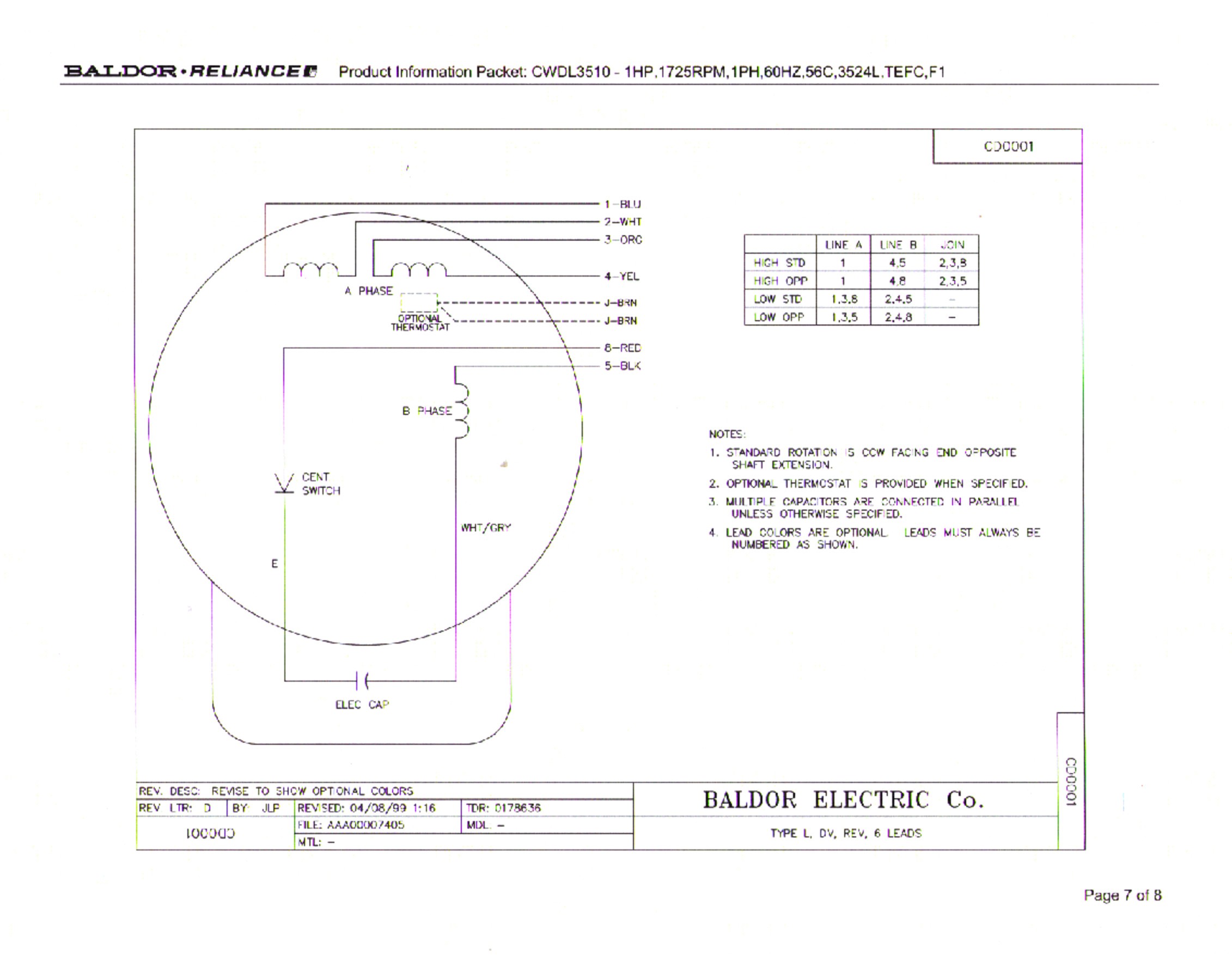
Lead Dc Motor Wiring Diagram. According to the wiring diagram of the stator winding, wound field DC motors are divided into: separately excited DC motor. Following is the schematic diagram of the DC motor.
Clamp with remote controller lead wires Attached wire (Control wiring) Attached wire (Power supply). (Note) If the fan rotates by entry of outside air, etc while the air conditioner stopped, the indoor unit may operate as the fan motor stops.
A common technique for doing this is to use an H-Bridge.

12 Leads Terminal Wiring Guide for Dual Voltage Delta ...

Weg Electric Motor Wiring Diagram - Complete Wiring Schemas
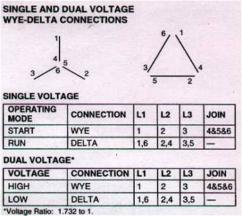
Wye Start Delta Run Motor Wiring Diagram Sample | Wiring ...

Electric Motor Single Phase Wiring Diagram - Wiring ...

China Gear Reducers Shaft Mount Reducers Wiring Diagrams ...

DC Motor Speed Controller Diagram | Electrical ...

54537d1340990049-how-reconnect-motor-480-volts-back ...

current - in order to understand bldc motors and their ...

Identifying Leads of a Twelve Lead Three Phase Motor
Living with the Lab Gerald Recktenwald Portland State University. gerry@pdx.edu. • Explain the role of a snubber diode • Describe how PWM controls DC motor speed • Implement a transistor circuit and Arduino program for. Arduino is basically an amazing micro controller. WIRING DIAGRAM A wiring diagram shows, as closely as possible, the actual location of all component parts of the device.

0 Response to "Lead Dc Motor Wiring Diagram"
Post a Comment