Volt Dc Motor Starter Wiring Diagram
Volt Dc Motor Starter Wiring Diagram. The average voltage depends on the duty cycle, or the amount of time the signal is ON. A pilot light can be wired in parallel with the starter coil to indicate when the starter is energized, indicating the motor is running.

Check Starter Motor Drive and Clutch.
Below are two examples of wiring diagrams for star delta starters from industry suppliers.

-first of a few question, new sb 9 owner wiring questions
Delco Electric Motor Wiring Diagram Collection

Changing old air compressor from 110 to 220v | Adventure Rider
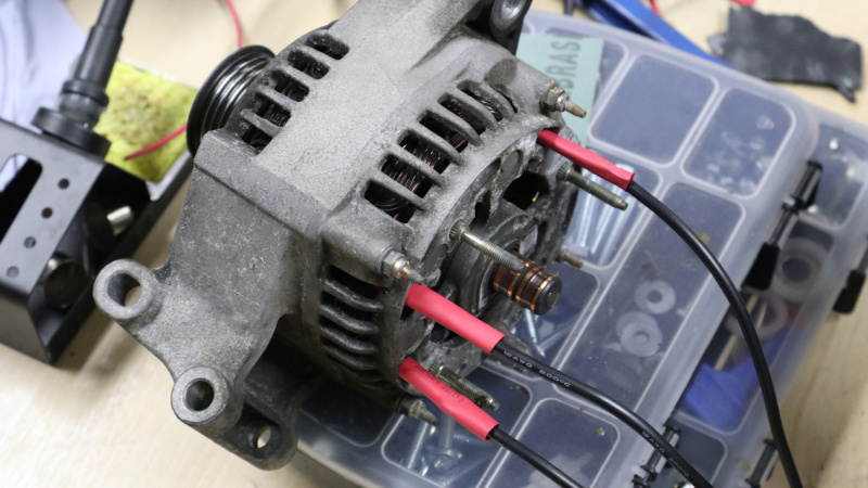
Car Alternators Make Great Electric Motors; Here's How ...

single phase motor: Wiring Diagram Single Phase Ac Voltage ...
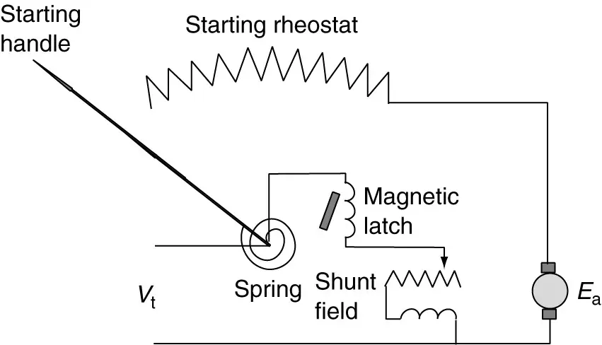
DC Motor Starters and Their Circuit Diagram | Electrical ...
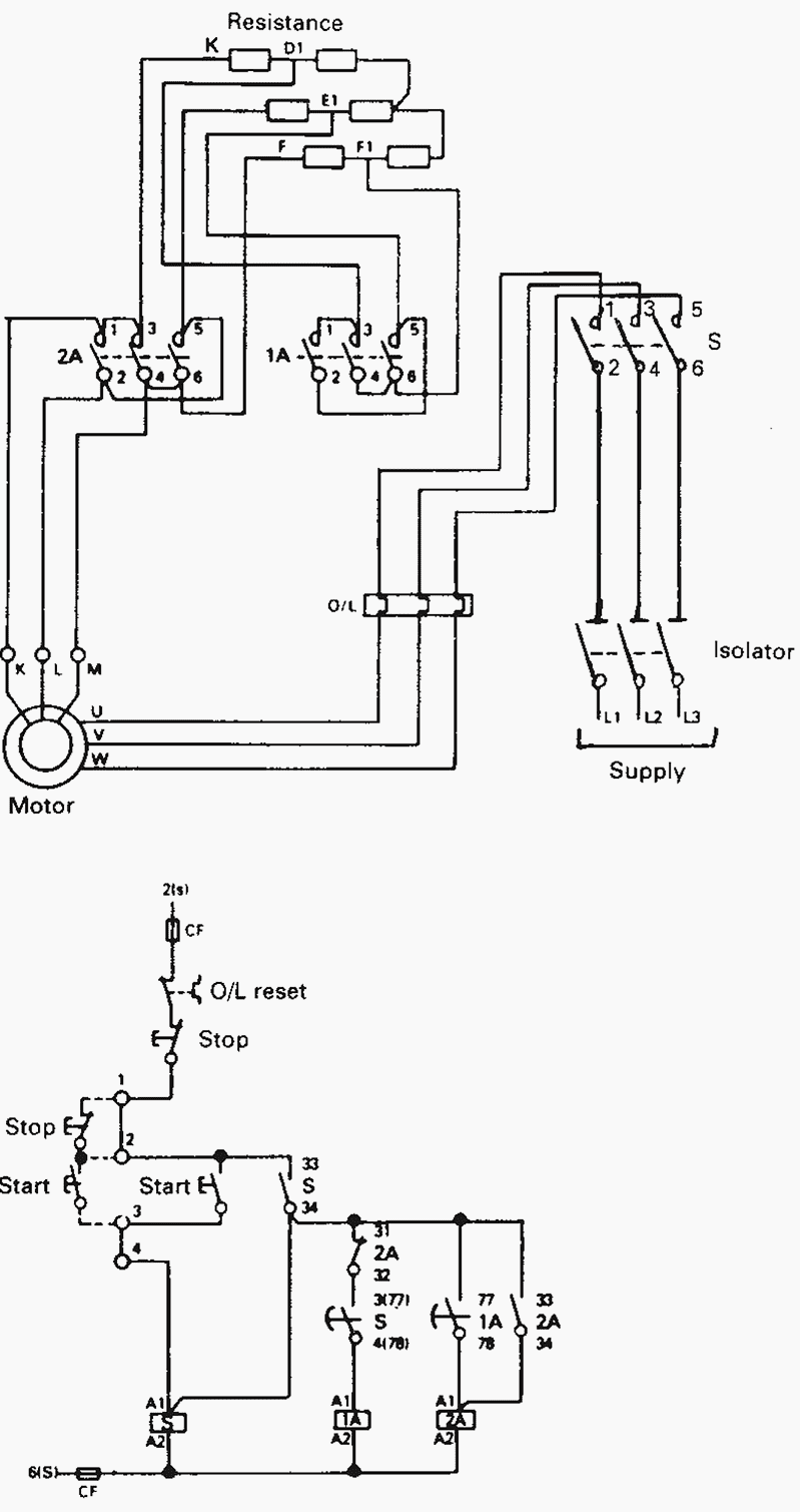
How to select contactors for use in direct on line starters

4 Pole Starter solenoid Wiring Diagram | Free Wiring Diagram

Wiring Manual PDF: 12 Volt Eton Solenoid Wiring Diagram
The diagram below shows a starter similar to the device described above, except that it uses current-triggered thyristors in place of a microcontroller. The average voltage depends on the duty cycle, or the amount of time the signal is ON. Circuit Diagram and Explanations: Circuit Diagram of this Bidirectional Motor Control Project is shown in image below.

0 Response to "Volt Dc Motor Starter Wiring Diagram"
Post a Comment