Lead Motor Wiring Diagram Iec
Lead Motor Wiring Diagram Iec. A multitude of other circuit combinations, not shown, should become apparent when reviewing the diagrams, as a. Black wires are conventionally used in power circuits and red wire in control circuits for AC magnetic equipment.

However your connections may seem a little different on the thermostat itself.
Select "Save Link As" or Save Target As" from the pop-up menu.
kettle Plug Fused Male IEC Lithium lead Acid Battery ...

Patent US5408154 - Motor connection block, particularly ...

Iec Motor Control Symbols | Electrical Wiring
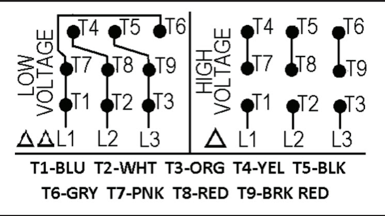
12 Lead Motor Wiring Diagram Dayton

Iec Motor Starter Wiring Diagram | Free Wiring Diagram

Iec Motor Starter Wiring Diagram Download | Wiring Collection

Find Out Here Weg 12 Lead Motor Wiring Diagram Sample

Iec motor starter wiring diagram - Economical home lighting

Iec Motor Starter Wiring Diagram | Free Wiring Diagram
They can be used as a guide when wiring the controller. Black wires are conventionally used in power circuits and red wire in control circuits for AC magnetic equipment. Representation of all the connections within the device or combination of devices.

0 Response to "Lead Motor Wiring Diagram Iec"
Post a Comment