Pin Plug Wiring Diagram
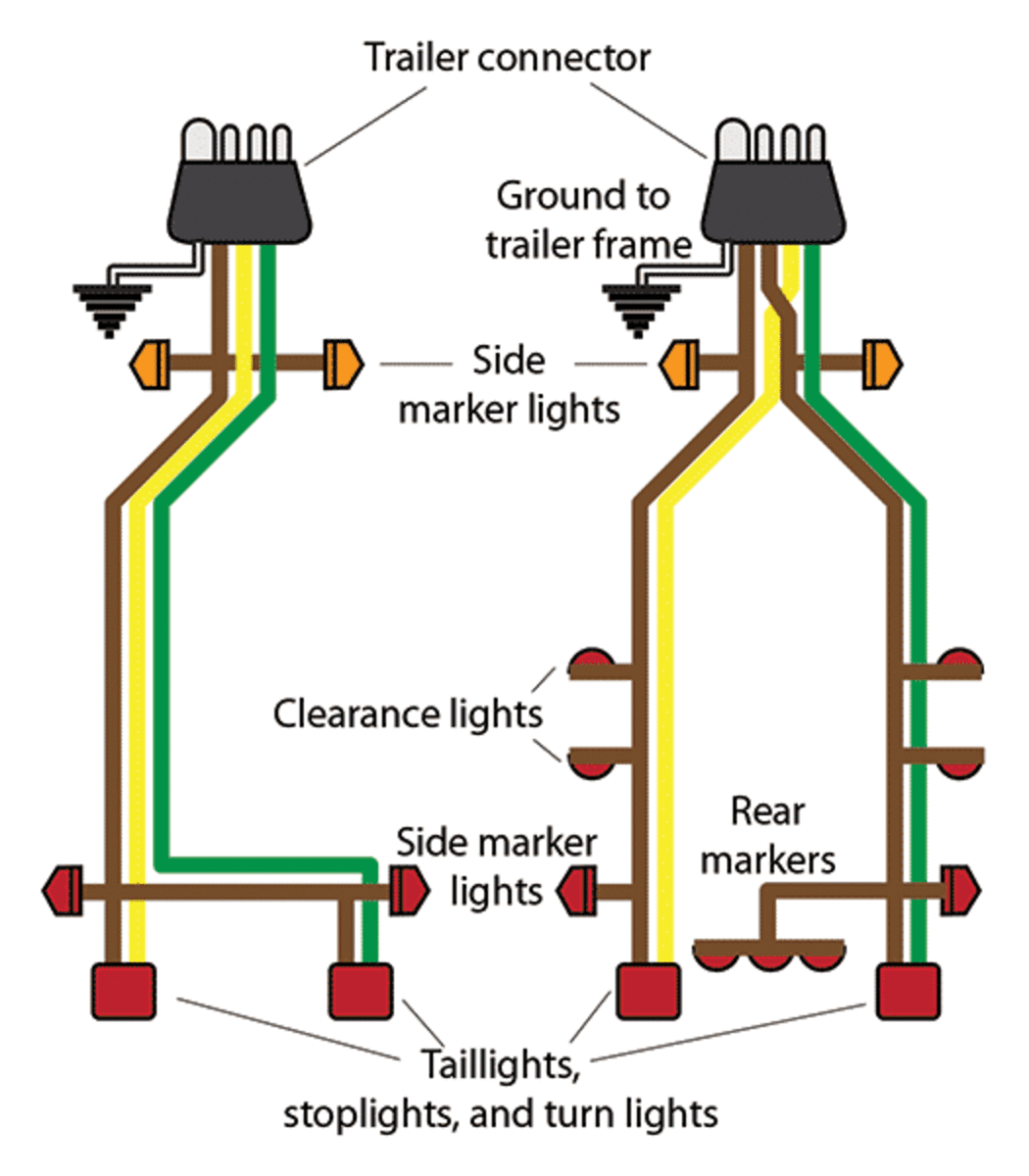
Pin Plug Wiring Diagram. On the other hand, this diagram is a simplified variant of the arrangement. If your vehicle is not equipped with a working trailer wiring.

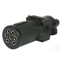
Here's the wiring diagrams showing the pin out for the plug and socket for the most common circle and rectangle trailer connections in use in Australia.
Work around this stuff long enough and you will see every possible variation in terms of color and.
The wall jack may be wired in a different sequence because the wires may be The jack should have a wiring diagram or designated pin numbers/colors to match up to the color code below. Should be black for + and white for -, but when I work on wiring my multimeter is God! This plug is wired to the trailer circuit.


0 Response to "Pin Plug Wiring Diagram"
Post a Comment