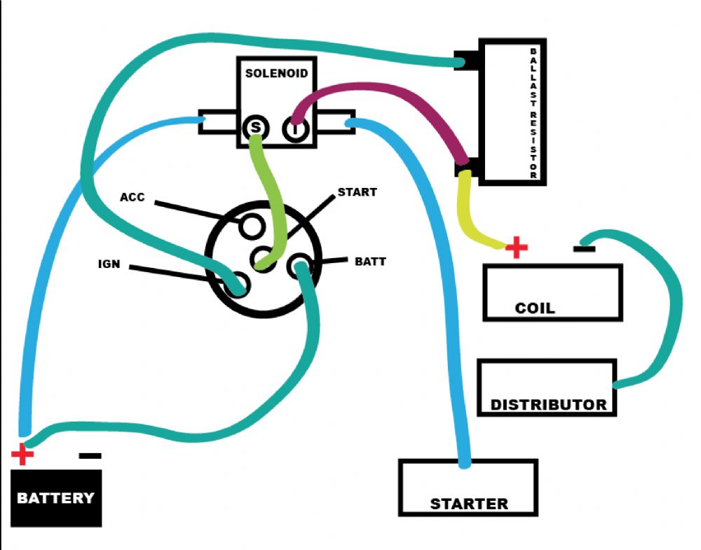
Volt Coil With Resistor Wiring Diagram
Volt Coil With Resistor Wiring Diagram. This is an exclusive section available only to our members. This is because the actual coils turns of wire being used to make it uses copper wire which has a resistive Transient Curves for an LR Series Circuit.

These diagrams represent a few possible ways you can snub EMI in an ignition coil driver.
Wiring diagrams and tech notes. • A ballast resistor is not necessary with any MSD Series Ignition but can be left in-line if originally equipped. • The MSD Blaster Coils and any other oil-filled, canister style coils should be mounted so that the high voltage coil tower is pointed upward.
Parallel and Series Resistor Circuit Analysis Worked Example using Ohm's Law Reduction Using Resistors in a guitar can add a whole new The Partial Split Resistor gives low-output humbuckers a stronger single-coil tone when split. Finding out how to read wiring diagrams is similar to learning a new language.


0 Response to "Volt Coil With Resistor Wiring Diagram"
Post a Comment