Valve External Voltage Regulator Wiring Diagram
Valve External Voltage Regulator Wiring Diagram. How to wire up a external voltage regulator for an alternator. Architectural wiring diagrams operate the approximate locations and interconnections of Wiring diagrams will moreover increase panel schedules for circuit breaker panelboards, and riser diagrams for special facilities such as fire alarm.

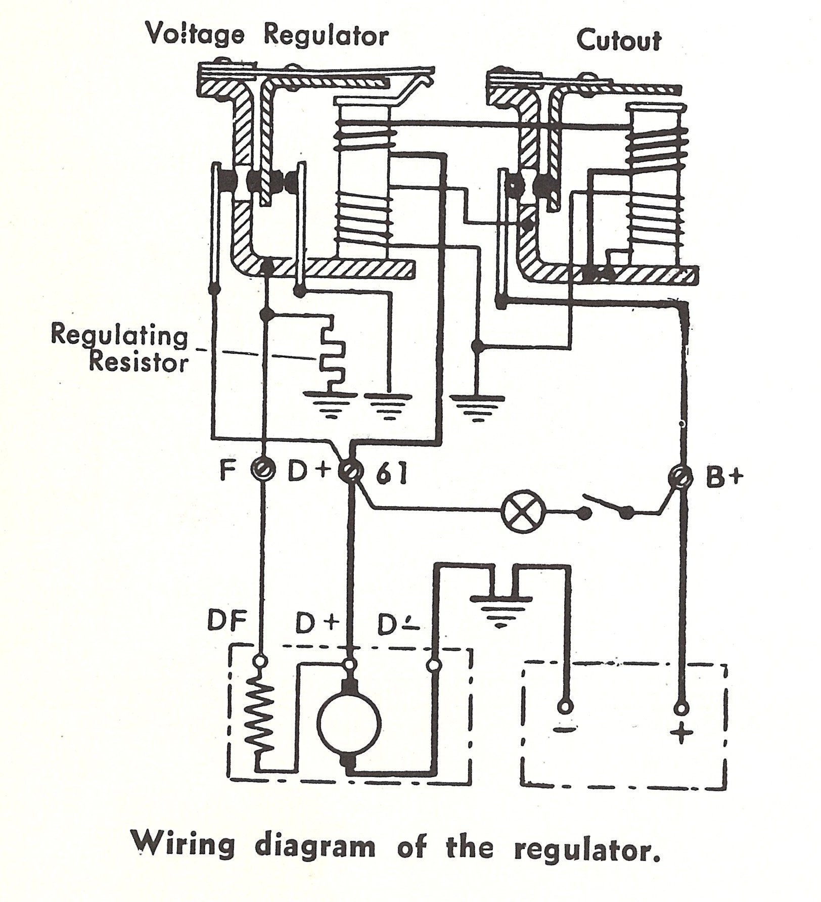
A voltage regulator is designed to automatically 'regulate' voltage level.
On the other hand, the diagram is a simplified version of this arrangement.
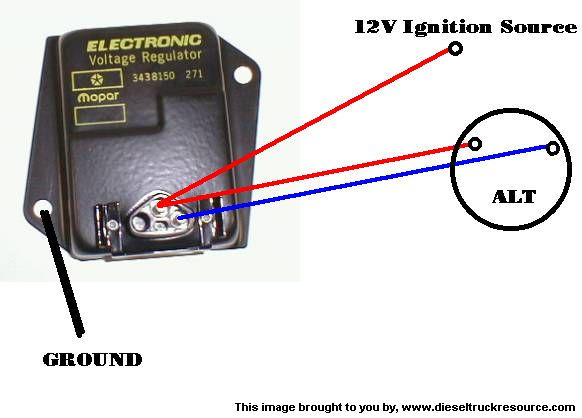
Chrysler Voltage Regulator Wiring Diagram
VW TRIKE WIRING
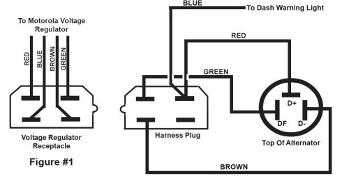
Delco Voltage Regulator Wiring Diagram 1972 - Wiring Diagram
Ford Alternator External Voltage Regulator Wiring Diagram ...

Ford External Voltage Regulator Wiring Diagram - Wiring Forums

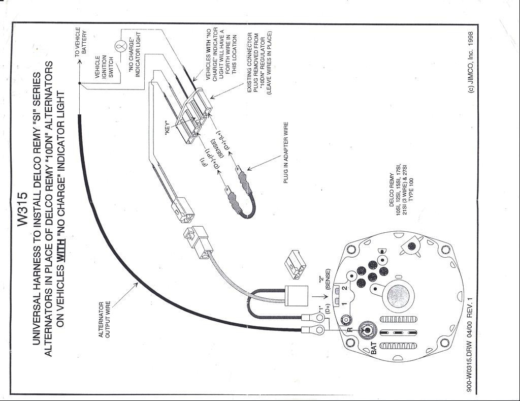
Alternator External Voltage Regulator Wiring Diagram

Toyota hilux external voltage regulator wiring

1991 F350 Ford External Voltage Regulator Wiring Diagram
Voltage Regulator Wiring Diagram | Wiring Diagram
I think they are telling you to check the resistances between the leads of the regulator. How to make an external voltage regulator for any car, truck, vehicle, or boat alternator. In the case where an external voltage regulator is used, if Voltage Regulator Control Source Configuration is set to.

0 Response to "Valve External Voltage Regulator Wiring Diagram"
Post a Comment