Lead 3 Phase Stator Wiring Diagram
Lead 3 Phase Stator Wiring Diagram. The bars forming the conductors along the rotor axis are connected by a thick metal ring at the ends, resulting in a Then, connect only the pulse signal and ground wires from the function generator to the HVDMC board. A three-phase AC induction motor is the only type where the rotating magnetic field is generated naturally in the stator because of the nature of the supply.
Advantage and disadvantage of this three phase inverter circuit.
In the circuit diagram all the transistor's flat surface may looks towards us but in real life it is not.

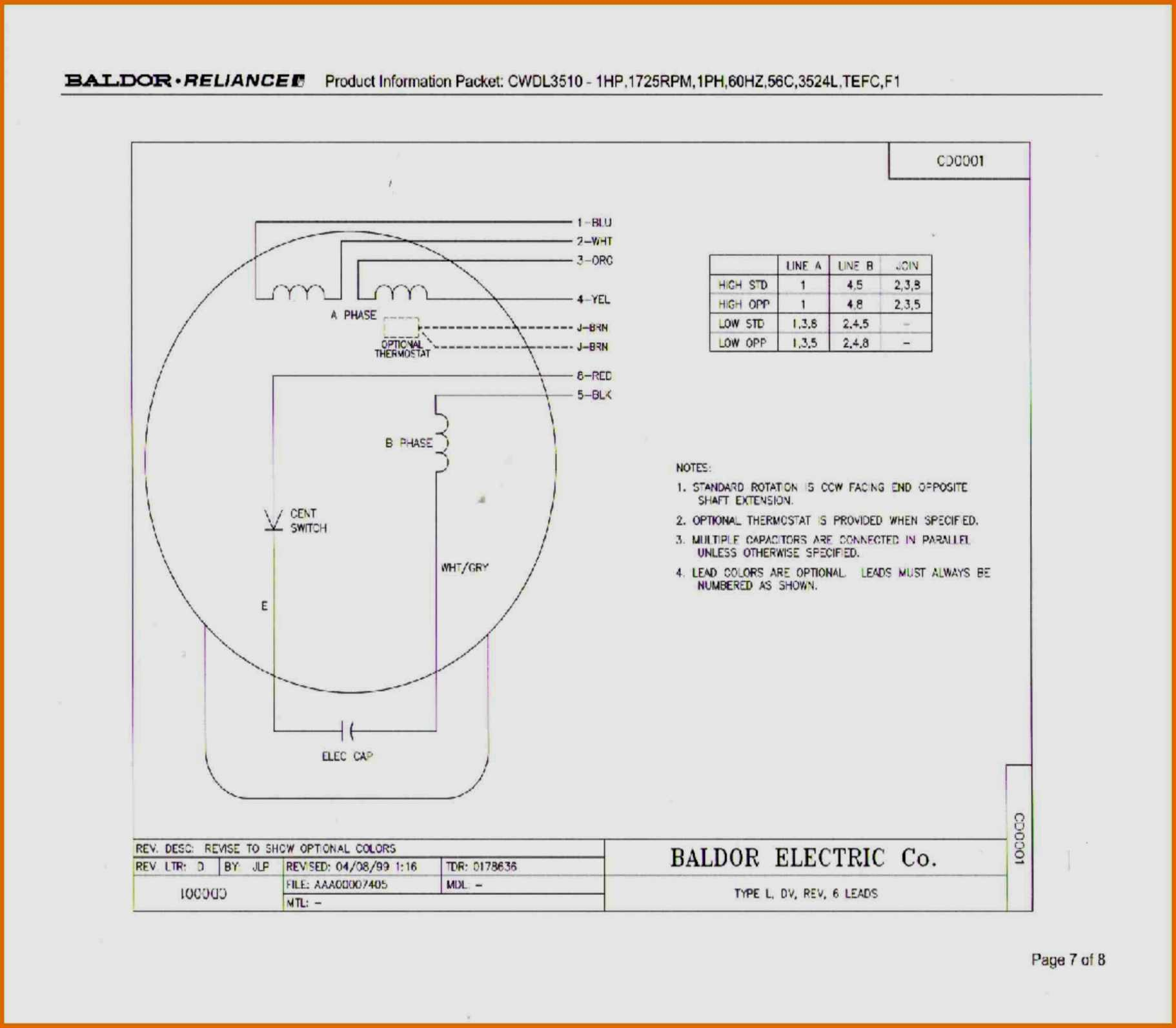
6 Lead Single Phase Motor Wiring Diagram With Capacitor ...
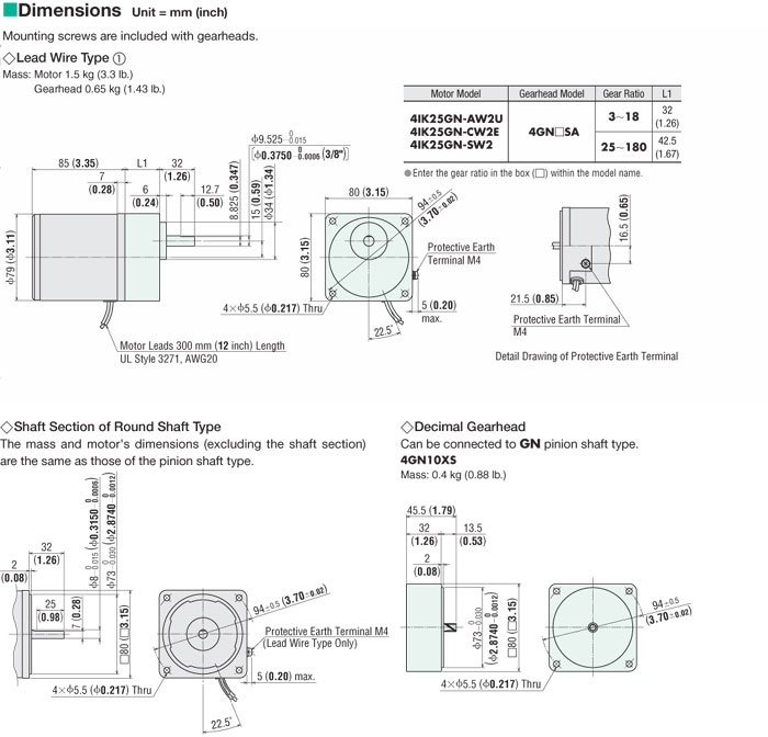
4IK25A-SW2 25 W (1/30 HP) Induction Motor (Three-Phase 200 ...

Stator 2 lead single phase 10 amp

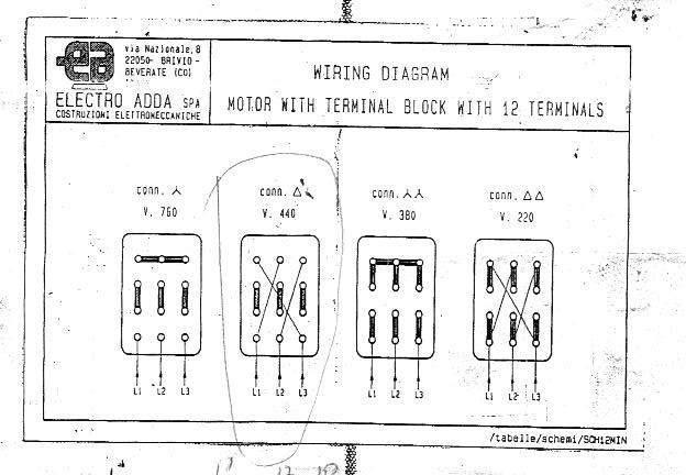
Wiring Diagram 4 Pole 12 Lead Motor | Wiring Library
[DIAGRAM] 6 Lead 3 Phase Motor Wiring Diagram FULL Version ...
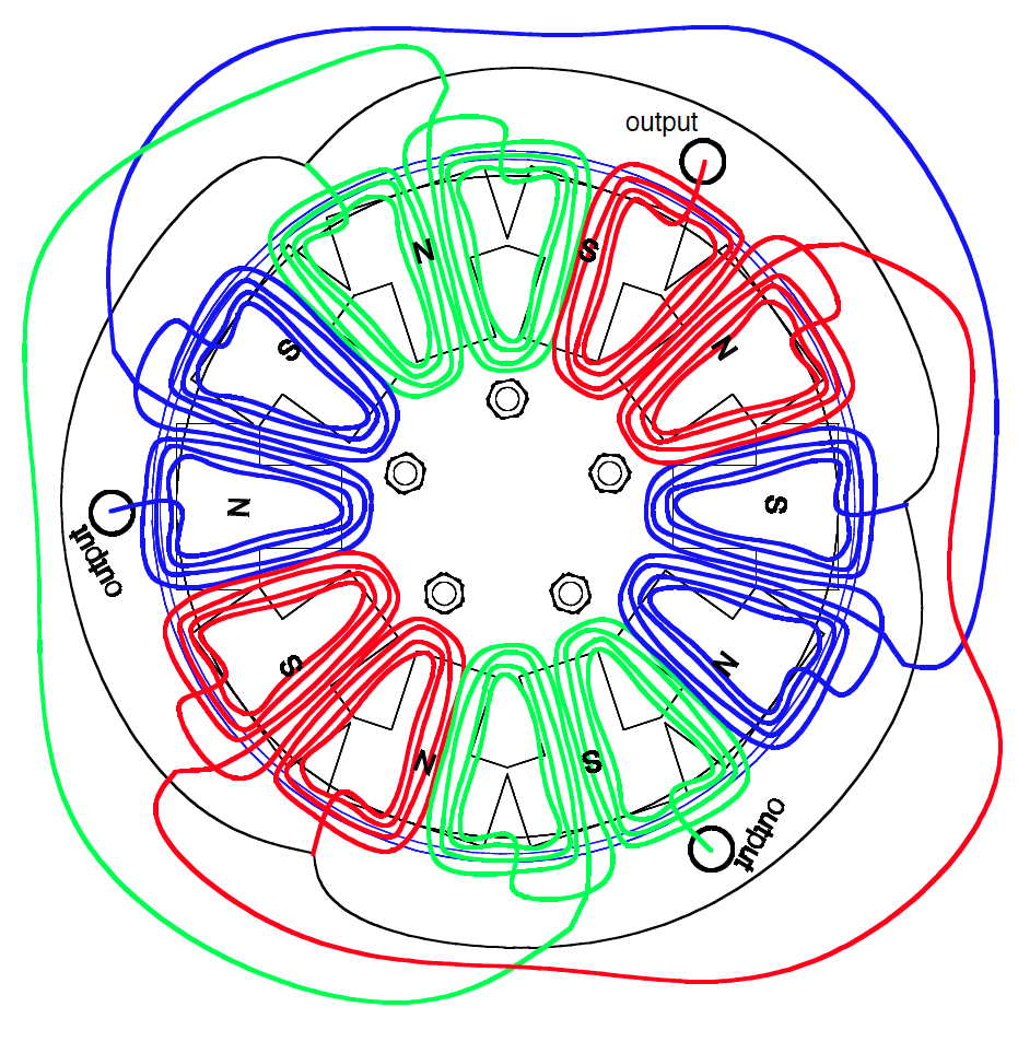
Clearer drawing of the 10-pole 12 coil design | Hugh ...
Weg Part Winding Start Wiring Diagram 12 Lead

Types of Single Phase Induction Motors | Single Phase ...

3 Phase Motor Wiring Diagram 9 Leads - Wiring Diagram Schemas
A three-phase AC induction motor is the only type where the rotating magnetic field is generated naturally in the stator because of the nature of the supply. Therefore, from wiring diagrams, you know the relative location of the components and just how they are connected. The general state diagram incorporates the main routine entered from reset and interrupt states.

0 Response to "Lead 3 Phase Stator Wiring Diagram"
Post a Comment