Volt Converter Wiring Diagram
Volt Converter Wiring Diagram. Normally Automotive Wiring Diagram Symbols refers to electrical schematic or circuits diagram. WIRING DIAGRAM A wiring diagram shows, as closely as possible, the actual location of all component parts of the Elementary Diagram (Common Control).
Onboard chargers are equipped with positive and negative leads for each battery.
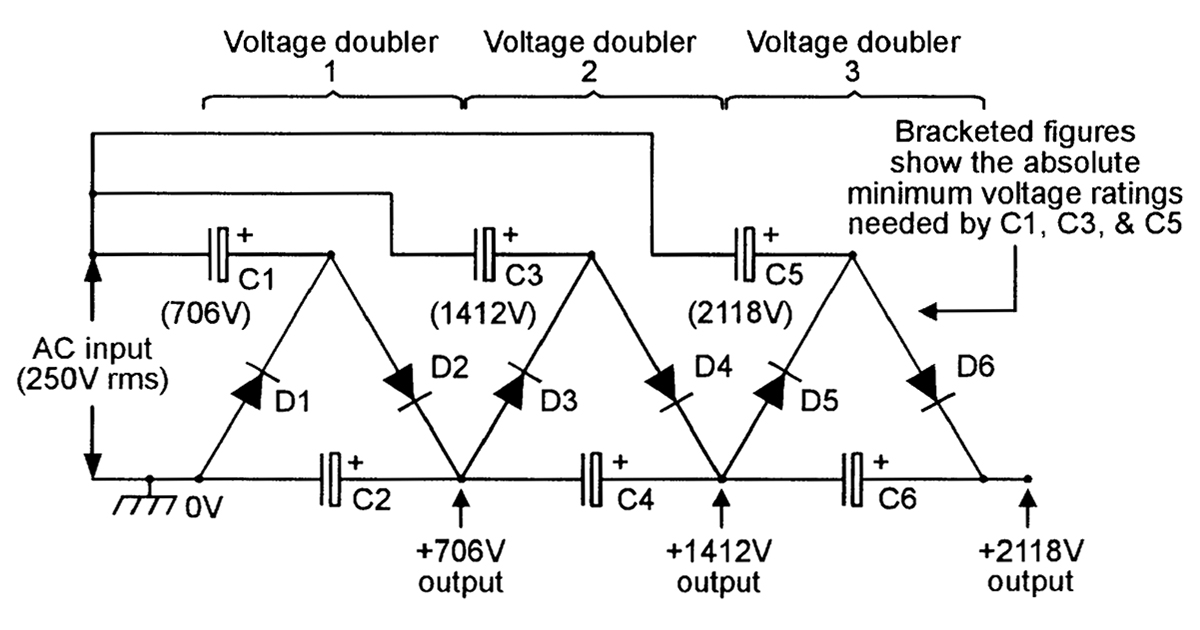
The schematic for this AC-DC converter circuit is simple.

8n Wiring Diagram 6 Volt - Wiring Diagram and Schematic

Low Cost Step Down Converter With Wide Input Voltage Range ...

Circuit diagram of the current to voltage converter IVC ...

9n 12 Volt Conversion Wiring Diagram | Free Wiring Diagram

FREQUENCY TO VOLTAGE CONVERTER CIRCUIT diagram
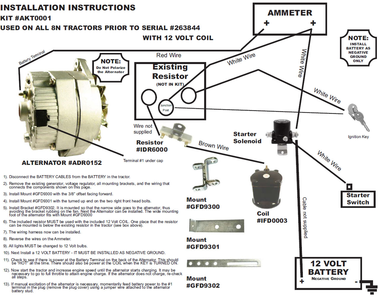
6 Volt To 12 Volt Conversion Wiring Diagram | Wiring Diagram

Airstream Converters and More
DC Voltage Converter Circuits | Nuts & Volts Magazine

[DIAGRAM] 12 Volt Converter Wiring Diagram FULL Version HD ...
It uses simplified conventional symbols to visually represent electrical circuits and shows how components are connected with lines. Here you will find the necessary wiring diagrams, schematics, circuits. Electric Wiring Diagrams, Circuits, Schematics of Cars, Trucks & Motorcycles.

0 Response to "Volt Converter Wiring Diagram"
Post a Comment